Interfacing of 8051 with DS1307 (RTC)
This post provides the code for
interfacing DS1307 RTC with 8051 microcontroller (e-g AT89C51 or AT89C52 etc).
This DS1307 RTC has i2c based interface and 8051 doesn't have
any built in i2c modules, so software i2c module is created in the
code. This code is written in C language using Keil uvision4 compiler. You
can download this code from the 'Downloads' section at the bottom
of this page.
The result of simulating the code in Proteus is shown below.
The result of simulating the code in Proteus is shown below.
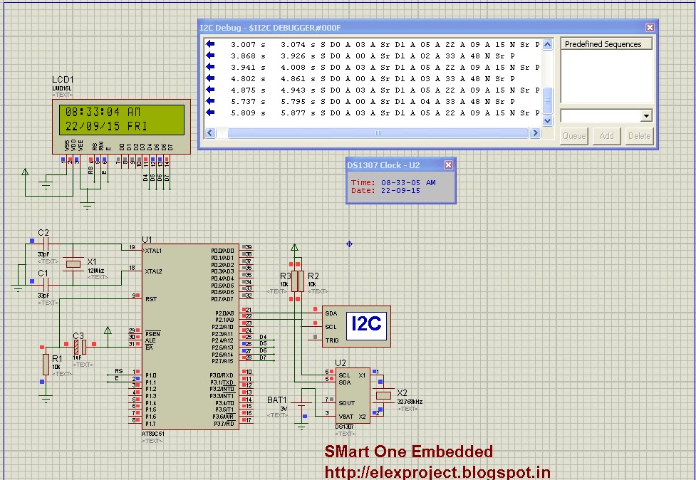 |
Figure 1. Interfacing
DS1307 RTC with 8051
|
In the above circuit[1], P2.0 pin is being used as SDA pin and P2.1 pin is the SCK pin.
Both of these pins are pulled up using 10K resistors as required for i2c
protocol. DS1307 RTC is the slave device, while 8051 is configured to be the
master. LCD is also attached with 8051, just to show the values received from
the RTC, otherwise it is not required in this circuit. Proteus provides
an 'I2C Debugger Tool' which is attached on the SDA and SCK pins in the
above circuit, this debugger shows all the activity on i2c bus[2]. It is attached in the circuit just for debugging purposes.
In the code, in the start a command is sent to DS1307 to set time to 8:32:59 AM and date to 2/11/12. After this, DS1307 starts to increment it's time after every second. Then new time is read from DS1307 RTC after every second and displayed on the LCD. Figure 1 was taken when time was 8:33:05 AM, which is correctly displayed on the LCD.
In the code, in the start a command is sent to DS1307 to set time to 8:32:59 AM and date to 2/11/12. After this, DS1307 starts to increment it's time after every second. Then new time is read from DS1307 RTC after every second and displayed on the LCD. Figure 1 was taken when time was 8:33:05 AM, which is correctly displayed on the LCD.
Code
The code for the main function is shown below.
 |
Figure 2. Main function
code for interfacing 8051 with DS1307 RTC
|
In the main function, firstly LCD is
initialized using InitLCD() function. Then i2c pins are
initialized using InitI2C() function. Then using Set_DS1307_RTC_Time(AM_Time,
8, 32, 59) function, a command is sent to DS1307 to set it's time to
8:32:59 AM. After that, Set_DS1307_RTC_Date(2, 11, 12, Friday) command
sets DS1307 date registers to 2/11/12 @ Friday date.
In the while(1) loop, Get_DS1307_RTC_Time() function reads current time from DS1307 and returns a pointer to an array which contains this current time, DisplayTimeToLCD() function takes this pointer as input and displays current time on the LCD in HH:MM:SS AM/PM format.
Also, Get_DS1307_RTC_Date() function reads current date from DS1307 and returns a pointer to an array which contains this current date, DisplayDateToLCD() function takes this pointer as input and displays current date on second line of the LCD in DD/MM/YY format.
Then there is a delay of roughly about one second using delay(65000); statement. This means that LCD is updated with new time and date after every second.
Using these simple 4 functions, Set_DS1307_RTC_Time(), Set_DS1307_RTC_Date(), Get_DS1307_RTC_Time(), Get_DS1307_RTC_Date() you can easily interface DS1307 RTC with 8051 microcontroller.
You can leave your comments and suggestions in the comment section below.
Notes and References
[1] In this circuit, 8051 is running at 1 MIPS speed using 12 MHz
crystal.
[2] 'I2C Debugger Tool' receives all the i2c messages and displays them on the 'I2C Debug' window. This 'I2C Debug' window is shown below in the figure.
[2] 'I2C Debugger Tool' receives all the i2c messages and displays them on the 'I2C Debug' window. This 'I2C Debug' window is shown below in the figure.
 |
Figure 3. I2C Debug window
|
In the above figure, 'I2C Debugger Tool' is telling us that
there were 4 sequences on the i2c bus, when this screen shot was taken. First
sequence "S D0 A 00 A 59 A 32 A 48 A P" is explained below.
·
S is
the starting bit sent from 8051(master) to DS1307(slave).
·
Then
0xD0 is sent to slave, this is the address of DS1307 RTC (As mentioned in it's
datasheet). Also, LSB bit of 0xD0 is zero, which means it is a writing command
for the slave. Slave sends an ACK after receiving this byte.
·
Then
0x00 is sent to slave, this is the starting address in DS1307 RTC on which we
want to write first byte. Slave sends an ACK after receiving this address byte.
·
Then
0x59 (it is the value of seconds) is sent to slave, this is the value we
want to save in DS1307 RTC on 0x00 address. Slave sends an ACK after receiving
this byte.
·
Then
0x32 (it is the value of minutes) is sent to slave, this is the value we
want to save in DS1307 RTC on 0x01 address. Slave sends an ACK after receiving
this byte.
·
Then
0x48 (8 is the value of hours, while 4 means it is 12 hour time format
with AM time) is sent to slave, this is the value we want to save in DS1307 RTC
on 0x02 address. Slave sends an ACK after receiving this byte.
·
Then
a stop bit (P) is sent to slave.
·
After
receiving this command, slave DS1307 sets it's time to 8:32:59 AM time.
Only the first sequence
is explained above, but you can easily understand remaining 3
sequences using the same approach as described above.
Downloads
The code was compiled in Keil
uvision4 and simulation was made in Proteus v7.10.
To download code and Proteus simulation click here.
To download code and Proteus simulation click here.
No comments:
Post a Comment